Swashplate mechanism of the R44

Thursday, January 27, 2011

6 comments
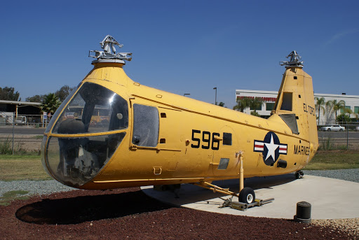
The Robinson R44 uses a semi rigid rotor system. This means that the rotor blades can move independently from the rest of the rotor in some directions. Rigid rotors don't allow any independent movement, forces are absorbed by blade flexing. Fully articulated rotor systems let the rotor blades move in even more independent directions, but this is usually used for helicopters with 3 or more rotor blades.

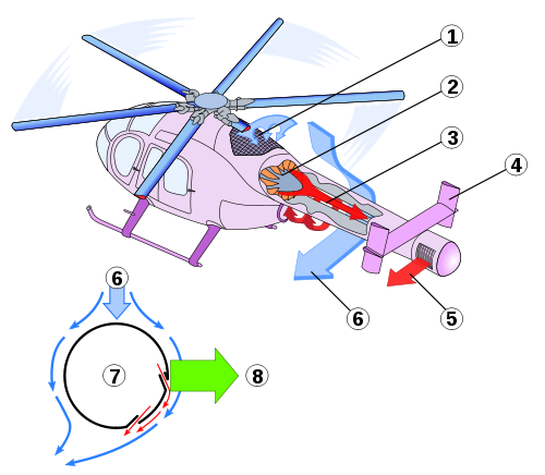
The next few images will explain how the swashplate mechanism is implemented in the R44, this is the mechanism that allows the helicopter to move in all directions.

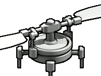
First of all, there's the rotor mast. The mast is responsible for turning the rotor blades and needs to be able to carry the weight of the helicopter. The rotor mast is connected to the transmission, which is in turn connected to a piston engine. Because rotor blades are designed for a specific rotational speed, the mast needs to rotate at that same. In the case of the R44, this speed is 550 RPM. Because the amount of resistance on the blades can vary (different wind conditions, different forward speed, hovering, ...), the throttle needs to be adjusted to maintain a near-constant RPM.

A ball joint is mounted on the rotor mast. This ball joint can move freely up and down the shaft.

The stationary swashplate is attached to the ball joint. This swashplate can tilt freely around the ball joint. The stationary swashplate consists of a lower and upper part, which are bolted together to clamp over the ball joint. Spacers are added between the lower and upper part to adjust the amount of friction. A specific amount of friction between the ball joint and the lower swashplate is necessary for optimal flight performance.

To keep the stationary swashplate from rotating with the rotor, a scissor mechanism is added. The scissor connects the swashplate to the fuselage. The scissor consists of 2 parts which are connected by a hinge. One end is connected to the helicopter using a hinge, while the other is connected using a ball joint. This means that the swashplate can move freely up and down, and can freely tilt in any direction, but can't rotate around the mast.

Three control rods are attached to the lower swashplate using ball joints. These rods are essential for being able to steer the helicopter. By independently pushing or pulling the rods, the height and tilt of the lower swashplate will change, which in turn changes the blade pitch, and the direction of the helicopter. The rods are connected to the helicopter controls mechanically, but a hydraulics system is in place to assist the pilot. This means that the helicopter can still be steered in case of a hydraulics failure.

A second swashplate is added on top of the lower swashplate. This swashplate is connected to the previous one by two angular contact ball bearings. The upper swashplate can rotate independently from the lower swashplate, but is constrained to the position and tilt of the lower swashplate, which is controlled by the control rods (and thus the pilot).

A second scissor mechanism is added. This scissor is nearly identical to the one that connects the lower swashplate to the fuselage. The only difference is that this one connects the upper swashplate to the rotor mast. This means that the upper swashplate will always follow the rotor blades.

A Teetering hinge is placed on top of the mast. The hinge is connected to the mast using a big bolt, because this bolt effectively carries the weight of the entire helicopter. This bolt also functions as the rotation point of the teetering hinge, which is why it's placed in the teetering hinge using two plain bearings made out of PTFE. The function of this teetering hinge is to reduce the mechanical stress on the rotor blades caused by the Coriolis effect. This is done by allowing the two blades to perform a seesaw movement: if one blade goes up, the other moves down, and the other way around.

Next, the rotor blades are attached to the teetering hinge. The blades are connected using a large bolt, which is again supported by two PTFE plain bearings. The blades can move up and down independently, this is necessary to reduce the mechanical stress on the blades from coning. Blade coning is the effect of the two main forces which interact with the blade: the lift force and the centrifugal force. Because the lift force can vary, the resulting force points in a different direction. This causes the blades to move to a different angle, depending on the position and tilt of the swashplates. In rigid helicopters, this is absorbed through blade flexing, in semi-rigid helicopters, a hinge lets the blades move freely. When the helicopter has landed, and the rotor is no longer spinning, there is no centrifugal force and lift force to keep the blades horizontal. The blades then rest on droop stops through small rods which extend into the teetering hinge.

To be able to steer the helicopter, the pitch of the blades needs to be adjustable depending on the position of the blade. This means that blades must be able to rotate along their length. Inside the bulge at the base of the rotor blade is a spindle assembly. This assembly contains 6 angular contact ball bearings, which allow the blade to rotate along the length, but keep them from being pulled out by the centrifugal force. At the base of the spindle, there's a rod which is used to control the blade pitch, this rod is called the pitchhorn. The pitchhorn is connected to the upper swashplate by a rod with ball joints. The rods push and pull the pitchhorn to change their rotation, thus changing the lift of that blade, and thus letting the pilot control the helicopter.

Types of main rotors

Saturday, December 4, 2010

0 comments
There are several different types of main rotor systems, and they are classified depending on how each rotor blade can move in respect to the main hub.

In fully articulated rotor systems, each rotor blade is attached to the main hub through a series of hinges, and each rotor blade can move independently of the others.The three possible movements are called flapping, leading/lagging, and feathering. These rotors usually have 3 or more blades.

The flapping hinge allows the rotor blade to move up and down, and is necessary to compensate for the asymmetry of lift.
The lead-lag hinge allows a rotor blade to move horizontally. The purpose of this hinge is to compensate for the acceleration and deceleration caused by the Coriolis-effect.
The last hinge is the feathering hinge, which allows a rotor blade to rotate along its length. Feathering is necessary to be able to change the lift generated by a rotor blade. Without a feathering hinge, it wouldn't be possible to control a helicopter.


Semi-rigid rotor systems are usually composed out of 2 rotor blades. The blades are connected to the main rotor shaft by a teetering hinge. The teetering hinge allows the two rotor blades to move up and down as a whole. When one blade goes up, the other goes down. Semi-rigid rotors don't have lead-lag hinges, so the lead-lag forces are absorbed through blade bending. These rotor systems do have feathering hinges though, because without them, the helicopter would be uncontrollable.


Rigid rotor systems only allow rotor blades to feather, all other forces are absorbed through blade bending.

Combination rotor systems are the most modern rotor systems, and may use the principles of all previous rotor systems. Some incorporate a flexible hub, which allows the blades to move without the need for bearings or hinges. They use flextures and elastomeric bearings to accomplish this. The advantages of this system include less maintenance, less vibrations, and a longer lifespan.


Source:
http://www.faa.gov/library/manuals/aircraft/media/faa-h-8083-21.pdf

Rotor blade materials

Tuesday, November 23, 2010

0 comments
The main rotor blades are a vital part of a helicopter, because they are responsible for supporting the entire weight of a helicopter. The forces on the rotor blades can increase even more when performing maneuvers, for example: pulling up at 1.5G means that the rotor needs to support 1.5 times the weight of the helicopter.


The first helicopter rotor blades were constructed out of laminated wood and fabric. One of the major drawbacks of using wood to construct the rotor blades is that wood absorbs moisture, which changes the mass of the rotor blade.

Wooden rotor blades were used up until the 1960s, until they were replaced by steel and aluminium. Advantages of steel and aluminium rotor blades is that they're cheaper and easier to produce, and that they do not suffer from moisture absorption. However, disadvantages include a low strength to density ratio and a poor resistance to fatigue.


Major improvements were made to the rotor blades by using composite materials. Composite materials are made by combining two different materials together. For example, glass fiber and plastic can be combined to form a composite material. The plastic binds the fibers together, and distributes the forces among them. The plastic also helps prevent the propagation of cracks. Composite materials are anisotropic, the material's properties depend on the direction of the fibers. Because of this, multiple layers are put on top of each other at 90° angles. Of course, glass fiber isn't the only material used in composite materials, carbon fibres, and many others are also used, depending on the specific requirements of the rotor blades.


Modern rotor blades start out with a core, made out of Nomex (a brand of aramid), or honeycomb aluminium, which is cut to size. Then, precisely cut pieces of composite materials are placed inside a mold, and are partially cured. The core is then placed within the mold, and is crushed into shape by a hydraulic press. The composite material is then cured using pressurized steam, and excessive material is trimmed off.


Rotor blades constructed out of composite materials can be up to 45% lighter than their metal equivalents, and they can be more easily manufactured in complex shapes.

Sources:
http://www.whystudymaterials.ac.uk/casestudies/helicopter.asp
http://www.madehow.com/Volume-1/Helicopter.html
http://www.advancedtechnologiesinc.com/rotor_blade_development.asp

Countering the torque effect

Monday, November 1, 2010

0 comments
There are several ways to counter the torque the rotor blades generate on the helicopter fuselage. The most common solution is the tail rotor, but that's not the only option.

NOTAR, "no tail rotor", is a system which utilizes the Coanda effect to redirect the air coming from the main rotor to the side, and thus counters the torque caused by the main rotor. Inside the tail boom is a fan which blows a high volume of air down the boom. The air exits the tail boom through slots on the side of the boom. This small air flow attracts and redirects the main air flow from the rotor, which in turn counters the rotor torque.


Normally, a rotor is driven by the mast, however the tip jet system makes the rotor blades turn using nozzles on the tips of the blades. The tips eject a gas in one direction and the blades move in the opposite direction. These two forces are action and reaction, and because of this, no torque is generated on the fuselage.


Another group of helicopters use several counterrotating main rotors, and because the rotors spin in opposite directions, no net torque is generated on the helicopter. Variations include coaxial rotors, tandem rotors, and intermeshing rotors.

Coaxial rotors

Tandem rotors

Intermeshing rotors


Sources:
http://en.wikipedia.org/wiki/Helicopter_rotor
http://en.wikipedia.org/wiki/NOTAR
http://en.wikipedia.org/wiki/Tip_jet
http://en.wikipedia.org/wiki/Tandem_rotors
http://en.wikipedia.org/wiki/Coaxial_rotors
http://en.wikipedia.org/wiki/Intermeshing_rotors

Cockpit controls

0 comments
Due to the innate complexity of flying in general, and helicopters in particular, there are quite a few controls necessary to pilot a helicopter.


First of all, there's the throttle. The throttle controls how much fuel goes to the engine of the helicopter. The rotor blades of a helicopter are designed to rotate at a specific speed. Because of this, it is necessary to be able to influence the power output of the engine by means of a throttle. This is controlled using a twist throttle on the collective control.

Next, there are the anti-torque pedals. These pedals control the pitch of the tail rotor blades. By changing the pitch, the tail rotor will produce more or less force, which causes the helicopter to yaw.


The collective control is a lever which moves the swashplate up and down. This causes the pitch of all the blades to change by the same amount, which means that this lever controls the lift of the helicopter. The collective control is usually at the left side of the pilot. The name is derived from the fact that it changes the angle of attack of all the blades collectively (i.e. at the same time).


Finally, there's the cyclic control. The cyclic control is the stick located between the pilot's legs and controls the tilt direction of the swashplate. The cyclic control changes the pitch of the blades cyclically (i.e. depending on the position of the blade in the rotation cycle). By pushing the cyclic forward, the helicopter will move forward. Moving the cyclic left or right will make the helicopter roll in that direction. Moving it backward will make the helicopter move backward.


Sources:
http://en.wikipedia.org/wiki/Helicopter_flight_controls
http://science.howstuffworks.com/transport/flight/modern/helicopter4.htm

How helicopters fly

0 comments
The first step necessary to achieve flight is generating a force which counters gravity. By moving an airfoil through the air, lift is generated due to the shape and angle of the airfoil. In the case of a helicopter, multiple airfoils are attached to a shaft, and by spinning that shaft, lift is generated.


This works well up until the moment the helicopter no longer touches the the ground. Newton's laws of motion dictate that to every action there is an equal and opposite reaction. This means that if the helicopter's rotor turns in one direction, the body of the helicopter will have a tendency to turn in the opposite direction. There are multiple solutions to this problem, but the most common solution is the tail rotor. The tail rotor generates a force which counters the helicopter's tendency to spin.


The next problem is movement, a helicopter with only the previous two mechanisms will only be able to take off and land. One way to make a helicopter move is by constantly changing the angle of attack of the blades. This in turn causes the blades to generate more or less lift on different parts of the surface the rotor blades cover, and this causes the helicopter to move.


This is implemented using a swashplate mechanism. The blades are connected to the rotor shaft using a bearing. A rod is also connected to the blade, and by moving this rod up and down, the blade rotates around its length axis. This means that the rod controls the angle of attack of the blade, and thus controls the lift the blade generates.


All these rods are connected to a ring-shaped plate around the main rotor shaft, and this rotating plate is then connected to a stationary plate using a bearing. Tilting the stationary plate causes the blades to different lift depending on their position, and this causes the helicopter to move. Moving the plate up and down changes the angle of attack of all the blades by the same amount, and thus allows the pilot to control how much lift the helicopter generates.


The combination of these mechanisms allow the helicopter to move in virtually any direction.

Sources:
http://en.wikipedia.org/wiki/Helicopter_rotor
http://en.wikipedia.org/wiki/Swashplate_%28helicopter%29
http://science.howstuffworks.com/transport/flight/modern/helicopter1.htm