Slideshow "How helicopters fly"

Thursday, January 27, 2011

1 comments

Fasteners and connections

1 comments


Because of the long lifespan of helicopters, all components need to be replaceable. For safety reasons, fasteners should not shake loose under the influence of vibrations. For those two reasons, nearly all components in a helicopter are fixed using locked nuts and bolts. Locking mechanisms used in the R44 are safety pins, safety wire, and adhesives. Plain bearings and ball bearings are either pressed into place, or held in place by a retainer ring and bolts.

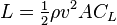
Strength calculation flapping hinge bolt

0 comments

Because of lack of data, approximations were used for the blade mass and center of gravity.

Source:
http://en.wikipedia.org/wiki/Robinson_R44
http://www.aviationwebdevelopment.com/samples/rotorbladecentrifugalforce.aspx

Annoted drawings and photos

0 comments


Forces acting on a helicopter

0 comments
 The three main forces acting on a rotor blade are the lift force, the drag force, and the centrifugal force. Lift is the upward force caused by the interaction between the air flow and the airfoil. Drag is the force of the air resisting the movement of the airfoil. The centrifugal force represents the tendency of the rotor blade to fly away from the center. Because of the circular motion, the air velocity is a lot higher at the tip of the blade than at the base. Because of the quadratic relation between lift and speed, and drag and speed, the lift/drag increases quadratically with respect to the distance to the center.


 Because of the forces on the rotor blades, the blades have a tendency to cone. This means they tend to tilt upward during flight. This is caused by the combination of lift and the centrifugal force. The centrifugal force tries to make the blade as horizontal as possible, while the lift tries to move the blade up. The combination of these forces mean that the helicopter blade is rotated slightly upwards. When the pitch of the blade is changed, the lift generated by that blade changes too, this means that there's a relation between the angle of attack and the coning angle. A tilted swashplate thus results in an asymmetric cone.


The motor of the helicopter makes the blades spin relative to the helicopter fuselage. However, because of action and reaction, this means that the fuselage has a tendency to spin in the opposite direction: this is called anti-torque. To alleviate this, another force needs to be generated outside of the central axis of the helicopter. In most helicopters, this force is the thrust from the tail rotor.


While in forward flight, the thrust generated by the blades depends on their position. Some areas will generate more lift than others, which means that the net result isn't a vertical force anymore. This net result can be split up in lift and forward thrust. The sum of the lift and the weight determine if the helicopter goes up, down, or hovers. The sum of the forward thrust and the total drag determine at what speed the helicopter moves forward.

Pictures

0 comments


Pictures of components

0 comments


The top picture shows the location of the PTFE plain bearings (shown in red) and the bolts which are used to attach the teetering hinge to the mast and the spindle to the teetering hinge (shown in blue). The plain bearings are attached to the teetering hinge by pressing them in. The bolts are 22mm in diameter, as they are effectively responsible for carrying the weight of the helicopter and keep the blades from being torn off by the centrifugal force. A variable amount of washers is added so that the friction of the flapping hinge can be changed. Because this bolt is such a critical component, the nut is locked in place using a safety pin.


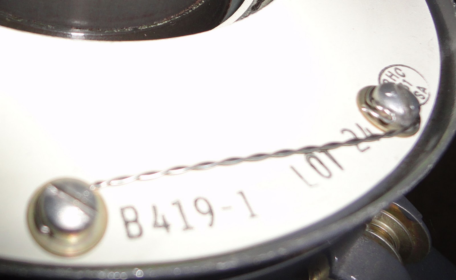
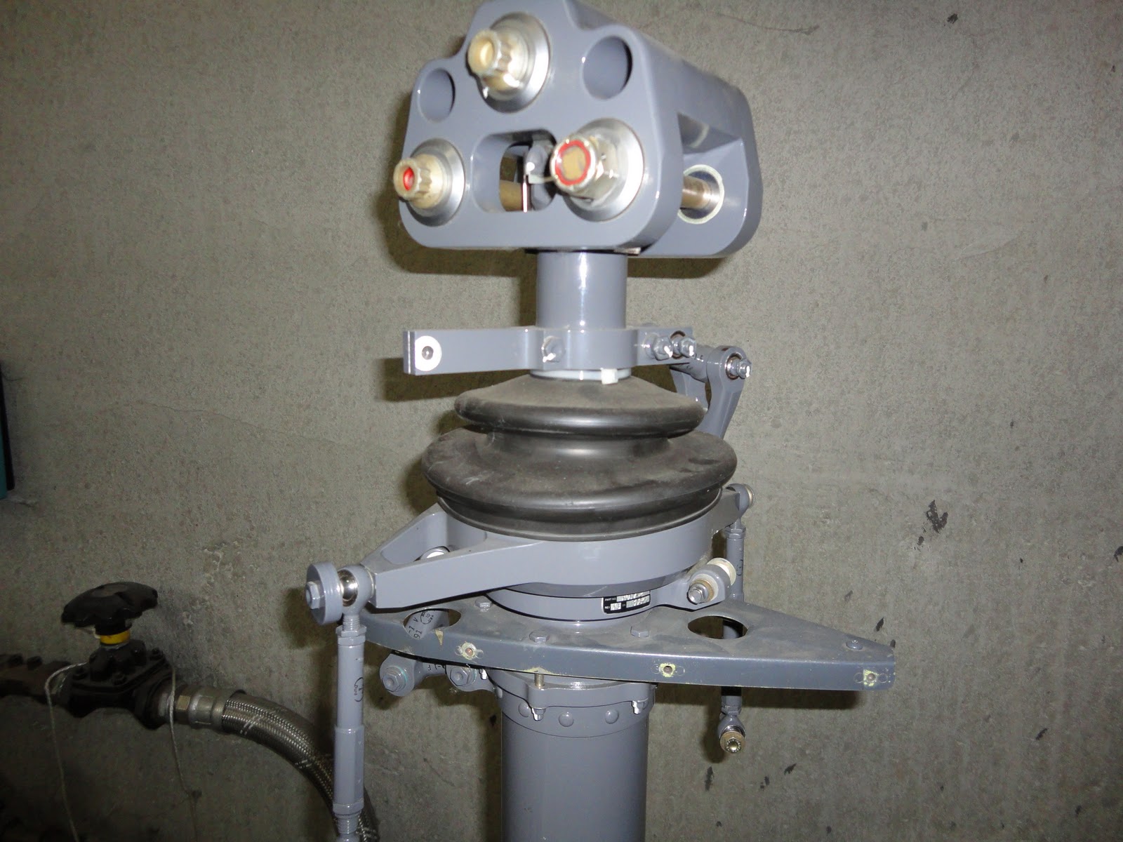
The rotor blade spindle contains 6 angular contact ball bearings. The bearings are necessary to allow change of the angle of attack of the blade. Angular contact bearings are necessary because they have both an axial and a radial load: the centrifugal force and the lift force respectively. The order in which the bearings need to be assembled is printed on the outer ring: a number from 1 to 6 and two sloped lines indicate this. The bearings are heated and slid over the spindle. When the bearings need to be replaced, they are removed using a hydraulic press. The spindle with bearings is pushed into a socket in the helicopter blade, and are then fixed using 12 bolts.