Fasteners and connections
1 comments
Labels:
Components,
R44


Because of the long lifespan of helicopters, all components need to be replaceable. For safety reasons, fasteners should not shake loose under the influence of vibrations. For those two reasons, nearly all components in a helicopter are fixed using locked nuts and bolts. Locking mechanisms used in the R44 are safety pins, safety wire, and adhesives. Plain bearings and ball bearings are either pressed into place, or held in place by a retainer ring and bolts.
Strength calculation flapping hinge bolt

Because of lack of data, approximations were used for the blade mass and center of gravity.
Source:
http://en.wikipedia.org/wiki/Robinson_R44
http://www.aviationwebdevelopment.com/samples/rotorbladecentrifugalforce.aspx


Forces acting on a helicopter
0
comments
Labels:
Airfoil,
Blades,
Forces,
Helicopter


Pictures of components
0
comments
Labels:
Components,
R44


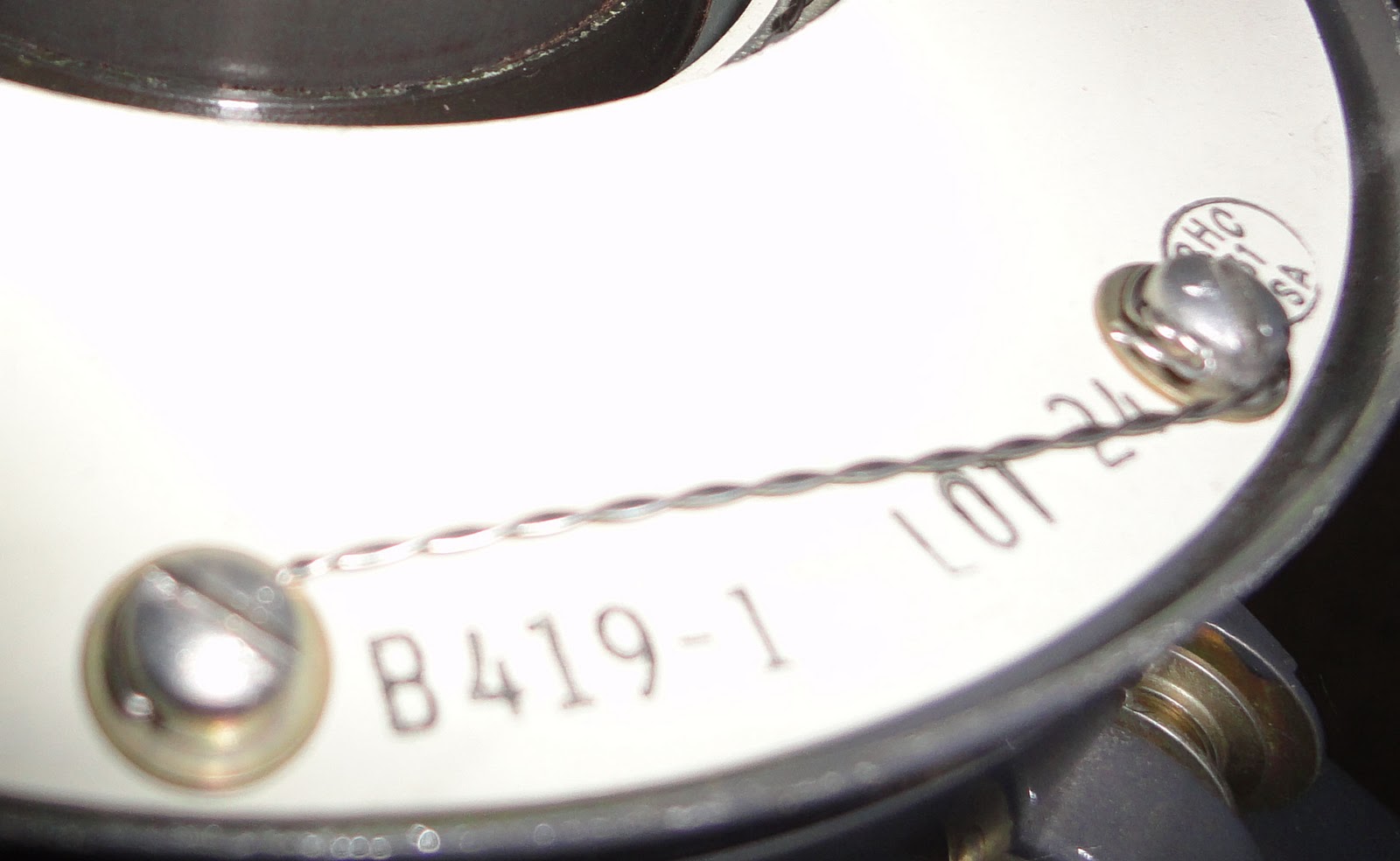
The rotor blade spindle contains 6 angular contact ball bearings. The bearings are necessary to allow change of the angle of attack of the blade. Angular contact bearings are necessary because they have both an axial and a radial load: the centrifugal force and the lift force respectively. The order in which the bearings need to be assembled is printed on the outer ring: a number from 1 to 6 and two sloped lines indicate this. The bearings are heated and slid over the spindle. When the bearings need to be replaced, they are removed using a hydraulic press. The spindle with bearings is pushed into a socket in the helicopter blade, and are then fixed using 12 bolts.
Swashplate mechanism of the R44
6
comments
Labels:
Mechanism,
R44,
Swashplate
The Robinson R44 uses a semi rigid rotor system. This means that the rotor blades can move independently from the rest of the rotor in some directions. Rigid rotors don't allow any independent movement, forces are absorbed by blade flexing. Fully articulated rotor systems let the rotor blades move in even more independent directions, but this is usually used for helicopters with 3 or more rotor blades.
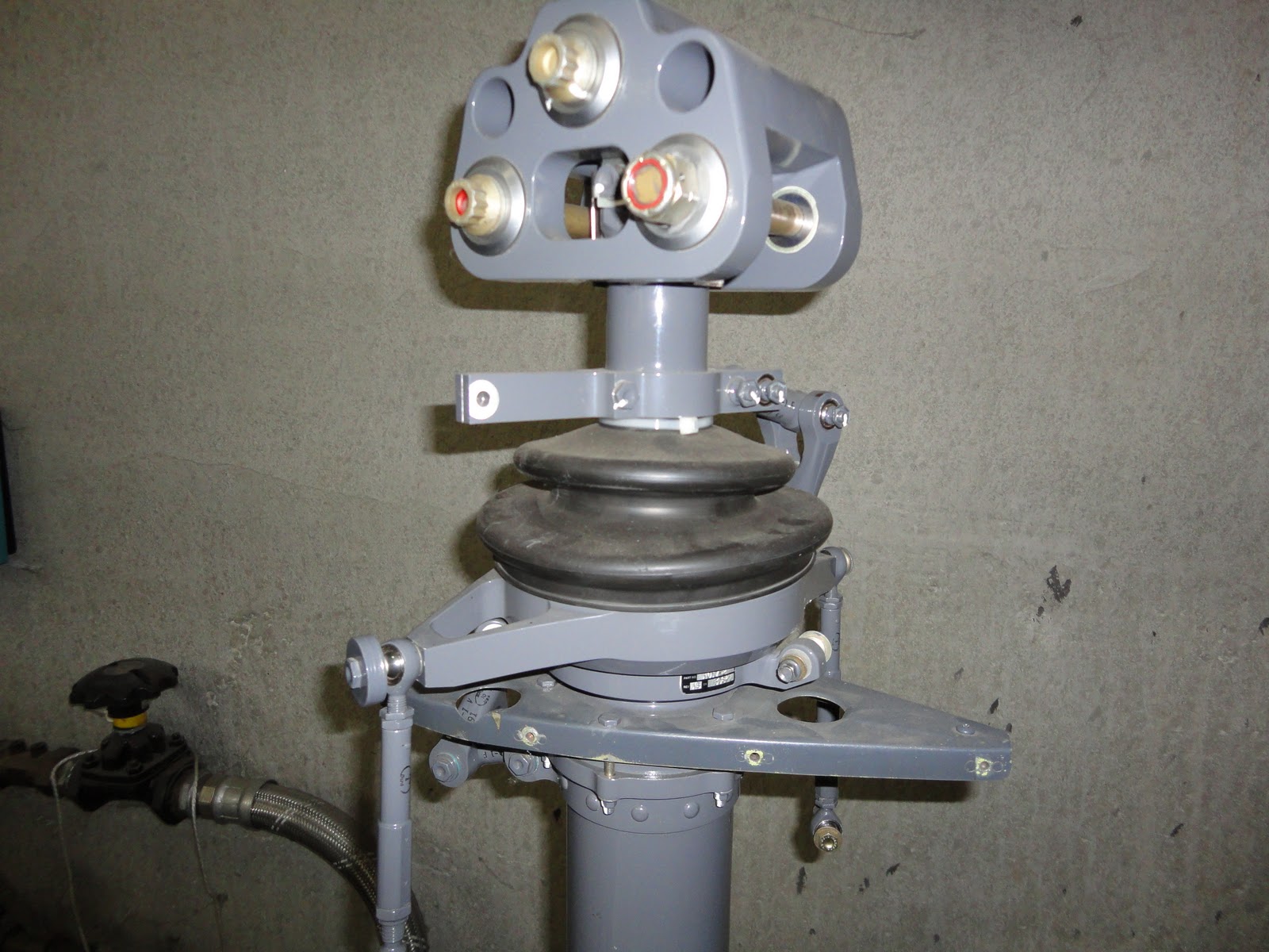
The next few images will explain how the swashplate mechanism is implemented in the R44, this is the mechanism that allows the helicopter to move in all directions.
 First of all, there's the rotor mast. The mast is responsible for turning the rotor blades and needs to be able to carry the weight of the helicopter. The rotor mast is connected to the transmission, which is in turn connected to a piston engine. Because rotor blades are designed for a specific rotational speed, the mast needs to rotate at that same. In the case of the R44, this speed is 550 RPM. Because the amount of resistance on the blades can vary (different wind conditions, different forward speed, hovering, ...), the throttle needs to be adjusted to maintain a near-constant RPM.
 A ball joint is mounted on the rotor mast. This ball joint can move freely up and down the shaft.
 The stationary swashplate is attached to the ball joint. This swashplate can tilt freely around the ball joint. The stationary swashplate consists of a lower and upper part, which are bolted together to clamp over the ball joint. Spacers are added between the lower and upper part to adjust the amount of friction. A specific amount of friction between the ball joint and the lower swashplate is necessary for optimal flight performance.
 To keep the stationary swashplate from rotating with the rotor, a scissor mechanism is added. The scissor connects the swashplate to the fuselage. The scissor consists of 2 parts which are connected by a hinge. One end is connected to the helicopter using a hinge, while the other is connected using a ball joint. This means that the swashplate can move freely up and down, and can freely tilt in any direction, but can't rotate around the mast.
 Three control rods are attached to the lower swashplate using ball joints. These rods are essential for being able to steer the helicopter. By independently pushing or pulling the rods, the height and tilt of the lower swashplate will change, which in turn changes the blade pitch, and the direction of the helicopter. The rods are connected to the helicopter controls mechanically, but a hydraulics system is in place to assist the pilot. This means that the helicopter can still be steered in case of a hydraulics failure.
 A second swashplate is added on top of the lower swashplate. This swashplate is connected to the previous one by two angular contact ball bearings. The upper swashplate can rotate independently from the lower swashplate, but is constrained to the position and tilt of the lower swashplate, which is controlled by the control rods (and thus the pilot).
 A second scissor mechanism is added. This scissor is nearly identical to the one that connects the lower swashplate to the fuselage. The only difference is that this one connects the upper swashplate to the rotor mast. This means that the upper swashplate will always follow the rotor blades.
 A Teetering hinge is placed on top of the mast. The hinge is connected to the mast using a big bolt, because this bolt effectively carries the weight of the entire helicopter. This bolt also functions as the rotation point of the teetering hinge, which is why it's placed in the teetering hinge using two plain bearings made out of PTFE. The function of this teetering hinge is to reduce the mechanical stress on the rotor blades caused by the Coriolis effect. This is done by allowing the two blades to perform a seesaw movement: if one blade goes up, the other moves down, and the other way around.
 Next, the rotor blades are attached to the teetering hinge. The blades are connected using a large bolt, which is again supported by two PTFE plain bearings. The blades can move up and down independently, this is necessary to reduce the mechanical stress on the blades from coning. Blade coning is the effect of the two main forces which interact with the blade: the lift force and the centrifugal force. Because the lift force can vary, the resulting force points in a different direction. This causes the blades to move to a different angle, depending on the position and tilt of the swashplates. In rigid helicopters, this is absorbed through blade flexing, in semi-rigid helicopters, a hinge lets the blades move freely. When the helicopter has landed, and the rotor is no longer spinning, there is no centrifugal force and lift force to keep the blades horizontal. The blades then rest on droop stops through small rods which extend into the teetering hinge.
 To be able to steer the helicopter, the pitch of the blades needs to be adjustable depending on the position of the blade. This means that blades must be able to rotate along their length. Inside the bulge at the base of the rotor blade is a spindle assembly. This assembly contains 6 angular contact ball bearings, which allow the blade to rotate along the length, but keep them from being pulled out by the centrifugal force. At the base of the spindle, there's a rod which is used to control the blade pitch, this rod is called the pitchhorn. The pitchhorn is connected to the upper swashplate by a rod with ball joints. The rods push and pull the pitchhorn to change their rotation, thus changing the lift of that blade, and thus letting the pilot control the helicopter.
The next few images will explain how the swashplate mechanism is implemented in the R44, this is the mechanism that allows the helicopter to move in all directions.


Subscribe to:
Comments (Atom)